BiSS – Bidirectional interface for Serial / Synchronous


BiSS encoder interface overview

The open-source BiSS Interface (Bidirectional/Serial/Synchronous) protocol implements a realtime interface. BiSS enables a digital, serial and secure communication between controller, sensor and actuator. The BiSS protocol is used on the lower sensor/actuator communication level in industrial applications (e.g. motor feedback, robotics) which require high-speed data transfer rates, safety, flexibility and a minimized implementation effort. In addition to its technical advantages, two conditions have established the current global standard: free BiSS license for applications and the stability and continuity of the protocol since its introduction.

BiSS follows the industrial trend of fully digital communication and increasing functional capabilities. It enables point-to-point topologies that are hardware compatible to the industrial standard SSI (Serial Synchronous Interface) and offers advanced features:

Minimum two unidirectional lines (clock and data) enable:

  • Cyclic high-speed data transmission (up to 10MHz with RS422)
  • Line delay compensation for high-speed data transfer on long transmission lines
  • Consideration of sensor processing times for data generation
  • Safety capability: CRC, Errors, Warnings
  • Daisy-chaining of multiple sensors within one slave device
  • Register communication with slave, e.g. for sensor configuration and calibration

Actuator data transmission and bus compatibility (daisy-chaining of several BiSS slave devices) with an additional data line MO (master to slave).

BiSS-interface_logo_760x290

BiSS system structure

A typical setup of a BiSS system with a BiSS master (e.g. drive/PLC) and BiSS slave (e.g. encoder/sensor) is shown in Figure 1. The position data is sent over a single cable from BiSS slave on the right to the BiSS master on the left. Besides power supply lines, two lines for differential clock signal transmission from BiSS master to slave and two lines for differential data transmission from BiSS slave to master are used to enable a robust and safe communication with RS422.

BiSS_Interface_Concept_Fig.1-point-to-point

Figure 1. BiSS point-to-point system structure based on a standard encoder and drive. Image courtesy BiSS Association e.V.

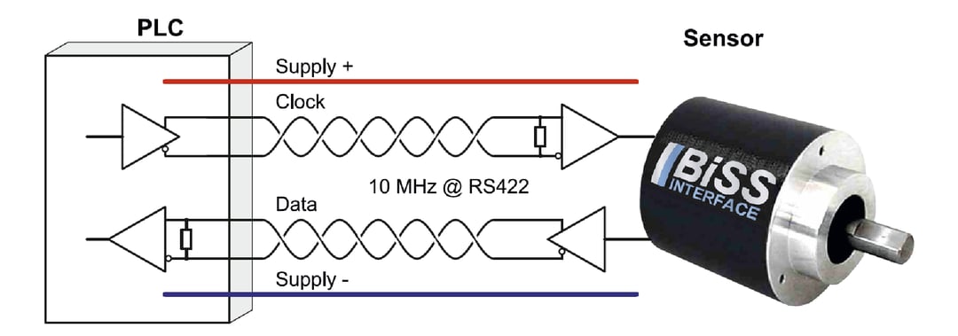
BiSS frame and features

BiSS_Interface_Concept_Fig.2-frame-and-features

Figure 2. BiSS Frame and Features. Image courtesy BiSS Association e.V.
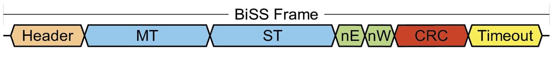
Latch point

Sensor data is simultaneously captured for all slaves in the daisy chain.

Line delay compensation

The BiSS master measures and compensates the total line delay in every frame. The line delay is measured from 2nd rising clock edge (MA) to falling data line edge (SL) and takes aging and temperature effects into account.

Slave processing time

In a point-to-point topology the slave delays the Start bit, if it requires time to prepare and provide its sensor data.

Data channel

Sensor and actuator data are transmitted as part of a data channel. Each data channel is defined by its communication parameters, e.g. transmission direction (sensor or actuator data), data length (0...64 bit), CRC polynomial. The BiSS master is configured accordingly to ensure proper communication.

Control communication

BiSS enables a bidirectional control communication via its unidirectional clock (MA) and data line (SL). In each frame the master sends one control data bit to the slave (CDM) and the slave responds accordingly (CDS). This in-band protocol can be used to perform register accesses to the slave without interrupting sensor data transfer. For example, it enables reading a sensor’s electronic datasheet, its temperature register or sensor calibration.

Timeout

Each BiSS frame is terminated by the slave’s timeout (stretching 0 at the end of the frame). The timeout is either a constant period (typically about 20μs) or depends on the clock frequency applied to MA (adaptive timeout). With the adaptive timeout, the timeout period is reduced at high frequencies.

BiSS communication profiles

Standardized communication profiles are defined for different applications, e.g. rotary encoders transmit angle position words as shown in Figure 3. The position word may contain the number of full mechanical revolutions (MT: multiturn information) and angle information within one mechanical revolution (ST: singleturn information). Validity of the position word can be indicated to the BiSS master with an error (nE) and warning bit (nW). Position, error and warning bit are protected against transmission errors with a standard 6-bit CRC.

BiSS_Interface_Concept_Fig.3-biss-frame-rotary-encoder

Figure 3. Typical BiSS Frame of a rotary encoder. Image courtesy BiSS Association e.V.


BiSS device identification

Control communication enables a BiSS master to access the slave’s memory. Typically, the sensor/actuator manufacturer stores product specific data, e.g. a manufacturer ID, device ID, serial number and a standardized electronic datasheet (EDS) in the slave’s non-volatile memory (e.g. EEPROM). The EDS contains all required parameters to successfully establish BiSS communication between master and slave and additionally provides application specific parameters. On power-up the BiSS master can then automatically read the EDS and configure itself accordingly.


This document is excerpted from the following document – 
BiSS Interface Concept published by the BiSS Association e.V.
Copyright © 2018, 2021 BiSS Association e.V.
biss-interface.com

BiSS-C downloads

download_blueREV 10000 – XML file for encoder purchased during 2019 and earlier

download_blueREV 10002 – XML file for encoders purchased during 2020 and later

See EtherCAT® Documentation below for additional PDF downloads.

EPC's BiSS C Encoders

arrow-alt-circle-right-regularCustomer Service


Questions? Give us a call at (800) 366-5412 or submit this form, and we'll contact you within one business day.

Expedite options are available on many models. Contact us for details.