wp_header-bg_circuit-board_1920x1080
White Paper | WP-2001

A New Approach to Interpolated High Resolution Encoders

Executive Summary

Encoder digital signals start as sine waves and can be interpolated to produce higher resolutions. Sine waves have to be clean and free of noise for effective interpolation. Be sure to use encoders that offer advanced optic and electronics systems to provide superior sine waves and interpolation.

Sine Waves

The key to the successful operation of an optical encoder is the optics system, which consists of a light source, a resolution disk, and a sensor. During the operation of the encoder, the resolution disk rotates between the light source and the sensor. Resolution lines on the disk break the beam of light between the light source and the sensor as each line passes by. The output from the sensor is an analog signal called a sine wave, a series of rising and falling voltages that varies with the amount of light reaching the sensor. Each sine wave period has a duration of 360 electrical degrees

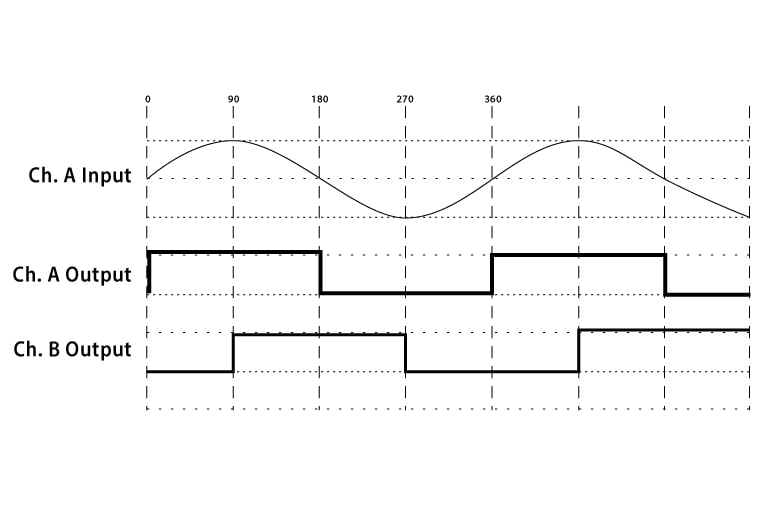
These sine waves are input to a comparator that generates the series of on/off states, or square wave signals, commonly associated with an encoder. For a single output “Channel A” encoder, the square wave is in phase with the original sine wave. If a second “Channel B” signal is needed, it is generated from another sine wave 90° offset from the original sine wave. An on or off state is generated based on the angle of each sine wave period. See Figure 1.

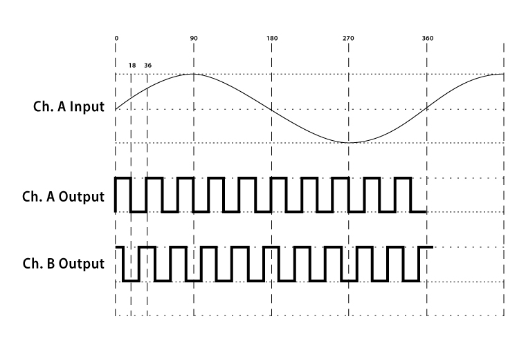
Since a sine wave is an analog signal, each sine wave can theoretically be divided into an infinite number of components that represent the various positions of the encoder. To achieve an interpolated resolution, the comparator is replaced by an interpolation circuit, which performs the actual division of the sine wave generated by the optics system into the desired number of multiple interim positions. The interpolator uses the angle of the sine wave period to maintain position integrity, so a pure sine wave is a requirement for good interpolation. The interpolation circuit then generates a new square wave output at the increased resolution. See Figure 2.

One on and one off position is created for each level of interpolation. For example, to achieve an interpolation level of 10X, the interpolation circuit creates 10 on and 10 off positions in each sine wave period, for a total of 20 positions. This means that one position is created every 18 electrical degrees (360÷20). See Table 1.

wp2001_figure1_sine_wave_1

Figure 1.

wp2001_figure2_sine_wave_2

Figure 2.

Signal Quality

Again, the most important factor in accurately generating an interpolated output is the quality of the analog sine wave signal input to the interpolation circuit. If the shape of the sine wave signal is distorted in any way, the interpolation circuit cannot accurately determine the angle of the wave. This results in pulses in the square wave that are shortened or missed altogether. EPC’s advanced optics system incorporates proprietary sensor design to ensure the cleanest possible sine wave. Using these high quality sine wave signals, EPC’s high-resolution encoders generate highly accurate and reliable interpolated outputs while virtually eliminating the phase, offset, and amplitude errors common in many other encoder designs.

Other Considerations

Once a clean interpolated square wave has been generated that accurately reflects the positional integrity of the encoder, the job is still not done. The rest of the encoder electronics must also be designed to accommodate the increased performance represented by good interpolation. For example, the 300 KHz output frequency of standard encoder electronics would only allow an interpolated encoder capable of 30,000 PPR to be used on a motor or shaft that was running at a maximum of 600 rpm (300,000 kHz/30,000 PPR*60). For that reason, higher speed drivers capable of operating to at least 1 MHz becomes a necessity. EPC has chosen a design that allows different drivers to be inserted so performance is balanced with economics, allowing an optimal solution.

Input Angle
within one sine wave

Output
0 - 18° ON
18 - 36° OFF
36 - 54° ON
54 - 72° OFF
72 - 90° ON
.......... ..........
342 - 0° OFF

Table 1.

Conclusion

Someone once said about playing the guitar, “It’s easy to play, but it certainly isn’t easy to play well.” The same thing can be said about interpolated encoders: with modern electronics, its not that hard to do, but it certainly is hard to do well. EPC’s various high-resolution encoders are just that – high resolution – and their innovative approach ensures that the gains made in resolution are not lost in increased inaccuracies and poorer performance specifications.

If you still have questions about optics, resolution, or anything else encoder-related, give us a call. When you contact EPC, you talk to real engineers and encoder experts who can answer your toughest encoder questions. You’ll get the right answers that make sense for your application.

Contact EPC today to get the information you need.

downloadDownload the PDF

Interpolated High Resolution Encoders