- Products
- Popular Products
- Safety Encoders
- Absolute Encoders
- Incremental Encoders
- Direct Replacement Encoders
- Encoder Kits for Large Motors
- Linear Measurement Solutions
- Programmable Incremental Encoders
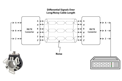
- Signal Enhancement
- Discontinued Models
- Index of All Products
- Accessories
- Accu-Coder Bore Inserts
- Anti-Rotation Flex Mounts
- Cables, Connectors, & Mating Cordsets
- Encoder Kits for Large Motors
- Flexible Shaft Couplings
- Gaskets & Seal Kits
- Hubs, Flanges, & Clamps
- Linear Cable Adaptors
- Models 30M & 30MT Accessories
- Measuring Wheels
- Mounting Brackets
- PR1 Programmer
- PR2 Programmer
- Protective Encoder Covers
- Safety Encoder Accessories
- Signal Enhancement
- TR2 Racks & Pinion Gears
- Tru-Trac Accessories
- Applications
- Sales & Technical Service
- Custom Engineering
- Resource Directory
- Global
- About
- Contact